Sunday, September 20, 2009

Networking Basic

Computer network is a group of interconnected computer that allows to communicate or exchange files and information. A typical computer network compose of Modem, Router, Switch, Work Stations and Network Printer as shown in fig1.


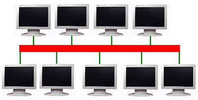
fig1. Typical Computer Network

Classification of Networks
Computer networks are often classified based on their connection type, topology, scale and technology that used to connect them.  

Connection Method
There are two common connection method that were used in computer networks, wireless and wired connection.  These two connection method differs on their structure.  A typical wired network used cables such as UTP (Unshielded Twisted Pair), Coaxial cables and Fiber Optics while wireless network doesn't used any cables they used radio signals or frequency to communicate to each other.  These two connection method each have advantages and disadvantages depending on your needs. One may serve you better and faster than the other. Always remember that in building a network you may need to consider the ease of installation, security, cost, reliability and performance.

WIRED NETWORK TECHNOLOGY

Wired network also known as Ethernet is a combination of cables and software that used to connect computer and other peripherals. It is typically more faster than wireless network and they can be very affordable but the cost of cables may add up to your expenses.

There are three basic things that you need to set-up wired network.
  • Cables
  • Hardware components
  • Network Interface Card (NIC)
    CABLES
    Cables are very essential in setting up wired network.  This will serve as medium for communication.  It will connect all the components in your network.  The following are the commonly used cables for wired networks,

    Unshielded Twisted Pair (UTP) - The most commonly used cable in computer networking. It is used in 10Base-T and 100Base-T networks, as well as in home and office telephone wiring. CAT 5 UTP was the standard cable for use with Ethernet 100Base-TX.


    fig2. Unshielded Twisted Pair (UTP)  cable


    The standard connector for UTP is RJ-45. This is a plastic connector that looks like a large telephone cable connector.  RJ stands for Registered Jack, implying that the connector follows a standard borrowed from the telephone industry.  As you can see on fig3, this connector has a  designated pin which wire goes inside the connector correspond to each color. 


    fig3. Pin assignment for T-568B and T-568A


    A standard CAT 5 UTP cable has two popular cabling scheme, Straight-through and Crossover. Straight-through cable is a CAT 5 UTP cable that has similar wiring in both ends. Both cable ends follow either T-568A or T-568B. It is also used to connect a computer to a hub or a switch.


    fig4. Straight-through cable


    Crossover cable is a CAT 5 UTP cable that has one end following T-568A and the other T-568B. A crossover cable is used to connect two computers directly and two hubs or switches.


    fig5. Crossover cable

    Shielded Twisted Pair
    (STP) - A type cable that is suitable for environments with electrical interference.  It protects cable from external EMI (Electromagnetic Interference).  Shielded twisted pair is often used on networks ing Token Ring topology. 


    fig6. Shielded Twisted Pair (STP)


    Coaxial Cable A type of cable that has single copper conductor at its center. A plastic layer provides insulation between the center conductor and a braided metal shield. The metal shield serve as a protector from outside interference such as EMI (Electromagnetic Interference). It is often used as a transmission line for radio frequency signals, computer networks and distributing cable television signals. 

    There are two types of coaxial cable a thick and thin coaxial cable. The thick coaxial cable can support segment length of 500 meters. It is also known as 10base5. On the other hand, the thin coaxial cable can support segment length of 200 meters and it is also known as 10base2.  The most popular connector for this type of cable is Bayone-Neill-Concelman (BNC).


    fig7. Coaxial cable


    fig8. BNC connector

    Fiber Optics Cable - It consists of a center glass core surrounded by several layers of protective materials.
    Optical fiber carries light on its transmission instead of electrical signals that makes it  more advantageous for long-distance communications.  This allows long distances to be spanned with few repeaters. The transmission is said to be high-speed, it can send information at higher data rates (bandwidth). For fiber optics cable that is specified for Ethernet communication also known as 10BaseF.


    fig9. Fiber Optic Cable

     
    HARDWARE COMPONENTS

    A typical wired network consist of the following hardware components:


    Router  - It is a networking device whose software and hardware are usually designed to the tasks of routing and forwarding information. It determines the next network point to which a packet should be forwarded toward its destination. The router joins two networks and decides which way to send each information. A router is located at any gateway (where one network meets another), including each point-of-presence on the Internet. A router is often included as part of a network switch.


    Switch / Hub - Although hub and switch use to connect multiple Ethernet devices together and making them act as a single network segment,  there still big difference between those two network device. Hub doesn't control any network activity or traffic. If the packet was sent to a particular destination, it sent throughout the network until the correct recipient receive it.  Unlike switch, once a packet was sent it will go directly to the recipient. Technically speaking, switch is more intelligent than hub.


    Modem -  Derived from the words Modulator - Demodulator. Modem is a network device that modulates digital information into analog signal and demodulates analog signal to digital information. It is used to connect a home or small network to internet.


    NETWORK INTERFACE CARD (NIC)
    A Network Interface Card (NIC) is used to connect computers to Ethernet.  They often called LAN card or Ethernet card.

     
    fig10. Network Interface Card (NIC)


    Network Topology
    Network Topology is a physical interconnection or layout of computers and other elements on a network. Network topologies are categorized into following  basic types:
    • Bus
    • Start
    • Ring
    • Mesh
    • Tree
    Bus topology - It is a type of network topology that use a common backbone to connect all computer and device on a network. The backbone serve as a shared communication medium. A typical Bus network use coaxial cable, it can be thinNet (10base2) or thickNet (10base10).


    fig11. Bus Topology


    Star Topology  - Is a type of network topology where a central connection (hub, switch or router) was used to connect all the computer and device in the network. It is very popular in small and home networks. This type of topology used CAT5 UTP cable.


    fig12. Star Topology

    Tree Topology -  This type of topology integrates a multiple star topologies together onto a bus.  It is a combination of star and bus topology that allows you to expand your network.


    fig13. Tree Topology

    Ring Topology  - It is a type of network topology where all the computer and device are connected and form a circle like shape. Each packet was sent around the ring until it reaches its destination. If there is a cable or device failure the loop breaks and it will cause network connection failure.


     fig15. Ring Topology 


    Mesh Topology -  A type of network topology where all the computers and devices are connected to one another. It allows full distribution of message around the network and it can take several possible paths from source to destination.


    fig15. Mesh Topology


    TYPES OF NETWORK


    Pear-to-Pear  - A type of computer network that has no intended client or host.  Both computer can be host and can be client at the same time.


    Local Area Network (LAN) - A computer network that covers small area such as home, office, small business and small building. They are widely used in connecting personal computers, printers and other network devices. A LAN is useful in sharing resources like files, games and other applications.


    Wide Area Network (WAN) -  A computer network that covers large geographical area like country and continent.  It also use transmission facilities provided by telephone companies.


    Metropolitan Area Network (MAN) -  A computer network that connects two or more Local Area Networks but not extend beyond city limits.


    Virtual Private Network (VPN) - A computer network that uses public network to connect remotely and securely to remote site or private networks. VPNs are frequently used by businesses and home offices. It is commonly used by people traveling or working from their home who want to connect to their company's network to check email or access business applications.


    WIRELESS TECHNOLOGY
    Wireless network is said to be the easiest and less expensive way to connect computer and other network device. The most popular among those wireless technology is wireless LAN (WLAN). 


    Wireless LAN connects computer and network device without the aide of cables it uses radio signals or frequency.  A typical WLAN use WiFi communication standard, among them are:
    • 802.11b
    • 802.11a
    • 802.11g
    • 802.11n
    802.11b - It is the first standard to be widely used in WiFi. It support maximum data rate of 11 Mbps and it has operating frequency of 2.4 GHz. The maximum range for indoor use is 150 ft or 45 meters and for outdoor use is 300 ft or 90 meters.


    802.11a - It is more faster than 802.11b and commonly found in most business networks. It supports maximum data rate of 54 Mbps. It has operating frequency of 5 GHz.  The maximum range for indoor use is 50 ft or 15 meters and for outdoor use is 100 ft or 30 meters.

    802.11g - The third WiFi standard that was ratified in 2003. It extend and improve 802.11b. It supports maximum data rate of 54 Mbps and operating frequency of 2.4 GHz. The maximum range for indoor use is 150 ft or 45 meters and for outdoor use is 300 ft or 90 meters.

    802.11n -  It improves upon the previous 802.11 standards.  It has a multiple-input multiple-output (mimo).  It has an operating frequency of 5 GHz or 2.4 GHz and a throughput 144 Mbps.  It supports maximum data rate of  600 Mbps.  The maximum range for indoor use is 300 ft or 91 meters and for outdoor use is 600 ft or 182 meters.


    There are two configuration of WiFi that is widely used today, ad-hoc and infrastructure.  

    Ad-hoc mode is a wireless configuration that allows connection in pear-to-pear mode.

    Infrastructure mode allows to communicate wireless device with a central base station (access point). It bridges communication between wireless network and wired network.


    Sunday, September 6, 2009

    Basic PC Troublesooting and Repair

    Troubleshooting and Repair are basically a method of finding the problem that causes the system not to work properly and later applying the possible solution. Successful troubleshooting requires a logical, consistent approach that seeks to narrow down the source of a problem by figuring out what is and what's not working until a single cause is identified.You cannot fix a problem by changing two or three object at once. It can cause serious damage to your computer. Patience is one characteristic of a good technician.


    Boot Failure
    Boot failure is one of the common problem in computer system. One possible cause of this issue is power supply and sometimes, each computer components can contribute more than we expected.


    The Computer is dead set
    Dead Set, in electronics, is basically no power or not enough power to make a device functional. The possible cause of this is power supply, groundings and busted components. The best way to deal with this is to check whether the computer has enough power. To do these check the following:
    • Power cable
    • Power supply
    • Soft power ON
    The Computer is ON but no system activity

    The possible cause of this issue is component failure. Basically, computer has a built in program, known as POST (Power ON Self Test), designed to test all component before boot process start. Normally, POST stops the boot process when a hardware problem occurs and the BIOS (Basic Input Output System) will issue an error message or a series of beep codes. Try the following to resolve that issue:
    • Restart computer and observe the POST. Usually, an indication that a computer has no problem is one short beep. If the technician will hear an abnormal beef codes there might be a problem with your system unit. Please refer to the list of beep codes in table 1.1.
    • Check motherboard for short.
    • Check CMOS reset jumper is on SET setting. Sometimes CMOS reset jumper can make the computer to stop from any system activity.
    • Test voltage output of the power good pin. This power good pin is usually used for resetting purposes so that the motherboard reset signal is kept active until the power good signal is raised to +5V. This keeps the motherboard not trying to do anything before the operating voltages have stabilized.


    INDICATION
    BEEP CODE
    ERROR
    Good
    1 short beep
    No Error
    Bad
    1 Long, then 2 Short Beeps
    Video Error
    Bad
    1 Long, then 3 Short Beeps
    Video Error
    Bad
    1 Long Beep
    Memory
    Bad
    Continuous Beeping
    Memory or Video Error
    Bad
    1 Long Beep
    Memory


    Table 1.1 - Common POST beep Codes


    The Computer is ON but has error message disk boot error, replace and Strike any key when ready boot error, replace and Strike any key when ready


    The main cause of this problem is booting on a non-bootable disk. If you encounter this error please try the following:
    • Check the floppy disk drive if there is any inserted disk.
    • Check if there's any USB flash drive that is connected in computer.
    • Check the boot sequence in Advance CMOS set-up. Make sure that the boot sequence is C:, CD-ROM, A: or the first boot device is Hard Disk Drive, second boot device is floppy drive and the third boot device is CD-ROM.
    • Make sure that you are booting in a valid system disk.
    • If none those steps resolve that issue, clone your Hard disk to a reliable source or make a clean installation of your Operating System. There might be a problem on the boot record of your operating system.


    Display Section Issue
    Display section may be divided into two areas – video card and monitor. Video Card is the component that is responsible for producing the visual output from your computer. It is also a piece of hardware that takes the visual output and tells the monitor which of the dots on the screen to light up (and in what color) to allow you to see it. The most common problem that you may encounter in display section is no video display. In order to deal with this we need to check the following areas:


    1. Check the Monitor
    • Make sure that the monitor has enough voltage or plugged into wall socket or to a computer power supply.
    • Check the monitor if it is turned ON. A LED Power indicator will indicate whether the monitor is turned ON or OFF. The LED Light will be ON if the monitor is turned ON.
    • Check if the video cable was connected to the video adapter port at the back of your computer.
    • Replace the suspected monitor with the good one.
    • If the following did not solve that issue check the video card and the rest of the components in your computer.
    2. Check the Video Card

    • If the POST beep code pertains to video card, remove the video card. Examine carefully. Look for signs of burn. Remove the dust in the slot carefully by blowing air directly to the slot then reseat the video card. Restart the computer and observe the POST. For some reason, video card fails because of the dust inside the computer and sometime those dust stick to the expansion slot.
    • If the above procedure does not fix the problem, replace the suspected video card with good one. Otherwise there is a serious problem in your system unit that can cause video card not to work properly. One possible cause is the motherboard. The video card slot (PCI, PCIE, AGP) in the motherboard may be busted and cannot recognize it.

    Hard Disk Drive (HDD)
    Hard Disk Drive (HDD) is a non-volatile data storage device that stores data on a magnetic surface layered onto hard disk platters. It can save large amount of data at minimum time compare to a typical floppy disk. The most common problem that you may encounter with hard disk drive is failed to detect by your computer. The following are the possible causes.

    • Power supply is unplugged or not connected to the drive.
    • Busted Drive electronics.
    • Damaged or unplugged IDE Cable.
    • Busted IDE Controller.
    • Disabled in CMOS set-up.
    • No hard disk is present.
    Try the following solution in an effort to resolve that issue:
    • Check CMOS set-up. In some instances, HDD may be disabled in CMOS Setting. To access CMOS set-up, restart computer press Del simultaneous to enter CMOS set-up. Go to Standard CMOS set-up check the status of your primary master, primary slave, secondary slave and secondary master and change their setting to Auto. Exit and save setting.
    • Check the HDD configuration. If possible try to change the present configuration of HDD if you suspected bad configuration. Sometimes, there are some HDD that can be detected to slave set-up only or master set-up only.
    • Check if the power supply is present and connected properly to HDD
    • Check if the IDE cable is properly connected. If the drive still undetected replace the suspected IDE Cable with good one.
    • Replace the suspected HDD with good one. This action can save time and can easily determine whether the HDD is defective or not.
    • If all of those solutions don’t fix the problem, we can conclude that the problem is in motherboard. The IDE Controller that was built in to the motherboard was defective.Replace the mother board with good one.
    • If your motherboard support SATA you can use SATA compliant HDD.
    Floppy Disk Drive (FDD)
    Floppy disk is the cheapest storage media that is available in the market. It is made of a magnetic disk enclosed in a plastic rigid container. In order to access the data that was stored in floppy disk a floppy disk drive (FDD) is needed. This two are very useful in our everyday computing but it can give inconvenience when trouble start. Most of the common FDD trouble is caused by floppy disk and the more serious comes from the drive it self.The following section will discuss some of the common FDD problems with its possible solution.


    Undetected Floppy Disk Drive
    The system fails to detect FDD because of the following:

    • Power supply is unplugged or not connected to the drive
    • Busted Drive electronics
    • Damage or unplugged FDD interfaces cable
    • Busted FDD IDE Controller
    • Disabled to CMOS set-up
    • No floppy Disk Drive
    In order for us to deal with that problem, we must consider all of its possible causes.Try to do the following solution:
    • Check the power supply connection of FDD. Turn On the computer and observe the POST as well the LED indicator at the FDD’s front panel. That LED will light for a short time once the FDD is detected and if enough power was establish to have system activity.
    • Check the FDD cable interface. Replace the suspected FDD interface cable with the good one to determine whether it is damage or not.
    • Check the CMOS set-up.In standard CMOS set-up look at the floppy disk tab. Check the status.The normal status is 3.5 inches floppy disk drive.
    • Replace the suspected FDD with good one before concluding that the FDD is defective. Doing this can save time and can easily determine whether the FDD is defective or not.
    • If all of those solutions don’t fix the problem, we can conclude that the FDD IDE Controller that was built in the motherboard is defective. Replace the motherboard with good one.
    Floppy Disk Issue
    More often, the cause of FDD problem is not with the drive but with the disk. As we all know floppy disk is made of plastic and the materials that was used in manufacturing it is not class A as we think off. The following are some Floppy Disk issue that you may encounter during computer operation.

    1. Access Denied - Your have tried to perform a write function to a read-only file. If using a floppy, make sure the disk is not write-protected. If you really want to delete the file, you can change it be a regular file, then delete it. In Windows 95, right click the file then choose Properties, then un-check the "Read-Only" box. In DOS, use the ATTRIB command.
    2. Attempted Write-Protect Violation - You tried to format a write-protected floppy diskette.
    3. Data Error Reading Drive X: - Usually caused by the slow misalignment of disk drives over time. Use a disk fixing utility to realign the disk's data.
    4. Disk Drive 0 Seek Failure - Drive 0 and 1 refer to your a: and b: drive. Most often, if you get this error it is because your BIOS are looking for a drive that is not there. Check your setup and be sure that only the floppy drives
    5. Disk Read Failure - Many potential problems. Try another disk. Make sure the cables are correctly attached to the drive. If all this is ruled out, your floppy drive is probably bad.
    6. Drive Not Ready - If this is a floppy drive, make sure the disk is inserted all the way. Try another disk. Make sure the floppy drive cable is not damaged. If this doesn't pinpoint the problem, you'll have to replace the floppy drive. You may have a bad sensor, so it can't sense a disk inside it.
    7. General Failure Reading Drive X: - First, press I for ignore, then use a diagnostic utility to test the disk. If this doesn't help, press A for abort, then inspect all cables related to the drive producing the error. If it a floppy, try another diskette.
    8. Non-Dos Disk Error Reading (Writing) Drive X: - The computer can't find a boot track on the disk. Boot off a floppy then use SYS to recopy the system files over.
    9. Not Ready Reading Drive X: - Usually, the cause of this is that the drive door of your diskette drive is not closed all the way. If it is, then you may have a bad sensor in your disk drive.
    10. Target Disk Is Write Protected - Often seen when trying to do a DISKCOPY to a write protected floppy disk. If the disk is not write protected, then that part of your floppy drive that senses write protection may be broken. Best bet is to buy another diskette drive.
    Keyboard Issues
    keyboard is an input device that used to enter information to computer. Using a keyboard, a person can type a document, use keystroke shortcuts, access menus, play games and perform a variety of other tasks. Although keyboard is very simple device in a computer system still it has issue that is can bring inconvenience in our everyday computing. The following are some keyboard issues that some computer user experienced:
    • Wrong characters appear when typing.
    • Onscreen messages do not appear when pressing multimedia keys.
    • Setting a multimedia button produces an illegal peration error message.
    • Multimedia keyboard buttons not working.
    • Internet keyboard buttons not working.
    • Sticking keys.
    The following are the common solution for those issues:
    1. The most common problem when faced with a non-working keyboard is an improper connection. Try reconnecting your keyboard, restart your computer and see if that fixes it.
    2. Turn off the system. Unplug the keyboard connect and inspect for any bent or broken pins. If the pins are bent, then it is possible to gently straighten them using the tip of a ball point pen or mechanical pencil. If the pins are broken, then replacement of the keyboard may be necessary.
    3. Try updating the device driver. Visit the manufactures web site for the latest driver available for your keyboard make and model.
    4. While at the manufactures web site. See if there are software patches or updates available for your keyboard. If there are, go ahead and install them as well as the updated driver.
    5. If you are using a multi-media type keyboard, be sure to delete the software before installing any new drivers for this type of keyboard. Install the updated driver for the manufactures web site, then re-install the keyboard software. If any software updates or patches are available for your multi-media keyboard, install them at this time. Delete the keyboard software by using Add/Remove Programs (Start > Control Panel > Add/Remove Programs). If you receive a prompt asking if you would like to remove all shared files, answer "No to all". Then click OK.
    6. If none of the above steps resolves your keyboard problem, it is likely that your keyboard is bad.
    Mouse Issue

    Mouse is a pointing device that will help you in navigating your computer screen. Your mouse senses your motion, when you click it sends them to the computer so it can respond appropriately. This section will cover some common mouse problem with its possible solution.

    Mouse is slow or erratic

    1. Clean the mouse.
    2. Check that mouse surface or mouse pad is clean and flat.
    3. Restart the computer.
    4. Change the mouse tracking speed


      • In Windows, Start  > Settings > Control Panel > Mouse > Motion.
      • In Macs, Apple Icon > System Preferences > Keyboard and Mouse.
    Mouse is not responding
    1. Check cords
    2. Unplug and re-plug the mouse.
    3. Ensure plugged firmly into Computer
    4. See if damaged or twisted
    5. Restart the computer
    6. Swap mice with another computer.
    Cleaning Trackball Mice
    1. Turn the mouse upside-down
    2. Remove ball cover.
    3. Remove mouse ball
    4. Clean gunk from the 3 rollers and mouse ball, using your finger or a paper clip as needed.
    5. Put ball in the mouse
    6. Secure the ball cover in place.
    Optical mice
    Some Macintosh optical mice (where the whole mouse is the button) will occasionally become stuck in the down position when they are new. Gently tapping the mouse will pop it back up. If an optical mouse is jumping around the screen, have the user remove the mouse pad and attempt to use the mouse. Sometimes the colors affect the performance of the optical mice.

    Friday, August 21, 2009

    Component Testing - Transistor

    Transistor is a three terminal semiconductor device that used to amplify electric current. This device is said to be one of the most greatest invention of man-kind in electronics because most of electronic gadgets and digital circuitry were composed of transistors. You can see transistor in a simple hand held radio, security system and even computers. There are two general types of transistor in used today - Bipolar Junction Transistor (BJT) and Field Effect Transistor (FET).


    fig1. Transistor in different packaging


    Bipolar Junction Transistor (BJT)
    A Bipolar Junction Transistor (BJT) is an active semiconductor device that is widely used as amplifier and a key component in most of high speed integrated circuit. It is composed of two coupled P-N junction. As shown in fig2, one P-N junction is in between collector and base while the other one is in between emitter and base. It is also a current controlled device because it can delivered a change in output voltage in response to a change in input current.

    fig2. A typical representation of Bipolar Junction Transistor (BJT)


    Classification of Bipolar Junction Transistor
    There are two classification of Bipolar Junction Transistor, NPN and PNP. NPN transistor is formed by introducing a thin region of P-type material between two regions of N-type material. Same thing with PNP transistor, it is formed by introducing a thin region of N-type material between two regions P-type material.


    fig3. NPN and PNP transistor


    Determining NPN and PNP transistor using Multimeter

    Note: We use Red probe as negative (-) and Black probe as positive (+)
    1. Set multimeter to minimum resistance range.
    2. Connect the positive (+) probe to base terminal and connect negative (-) probe to collector or emitter terminal.
    3. If the multimeter needle deflects on either connection it is NPN transistor.
    To determine PNP transistor reverse the polarity of multimeter probe connection.

    Transistor Testing
    Note: We use Red probe as negative (-) and Black probe as positive (+). Please set multimeter to minimum resistance. Remove transistor from its circuit.

    There are three indications of bad transistor Open, Shorted and Leaky.

    Open transistor will give you infinity resistance reading when measured all resistance in base-emitter terminal and base-collector terminal. The needle remains stationary and will not deflect at all.


    fig4. base-collector resistance reading for open transistor


    fig5. base-emitter resistance reading for open transistor


    Shorted transistor will give you zero ohm resistance reading when measured all resistance in base-emitter terminal, base-collector terminal and collector-terminal terminal.


    fig6. collector-emitter resistance reading for shorted transistor


    fig7. base-collector resistance reading for shorted transistor


    fig8. base-emitter resistance reading for shorted transistor


    Leaky transistor will give you resistance reading when collector-emitter terminal resistance is measured. Please take note that resistance between emitter and collector should be infinity or needle should not deflect at all because transistor should not conduct at all.


    fig9. collector-emitter resistance reading for leaky transistor


    As shown in fig10, 11 and 12, good transistor should have the following resistance reading:


    fig10. collector-emitter resistance reading for good transistor


    fig11. base-emitter resistance reading for good transistor


    fig12. base-collector resistance reading for good transistor


    For PNP Transistors reverse the polarity of your multimeter test probe.

    Tuesday, August 18, 2009

    Component Testing - Diode

    Diode is a two terminal semiconductor device that allows current to flow in only one direction. Its terminal was called Anode and Cathode.

    fig1. diode terminals Cathode and Anode


    DIODE TESTING
    Diode testing is very easy if you know some basic things about it such as biasing and meter polarity. As you can see in fig1, when a diode is connected in forward biased the flow of current will allow while on the other hand it oppose the flow of current. This only means that diode should be connected in forward biased so that the flow of current is possible. This biasing plays vital role in diode testing.


    fig2. Forward and Reverse Biased

    Multimeter polarity is another factor that we need to consider in testing diodes. Most of the analog multimeters have a leds that was reversed in polarity. The black led is positive (+) and the red led is negative (-). In this article we treat the red led as positive (+) and black led as negative (-) to show how diode biasing play its role in diode testing.

    To test diodes please follow the steps below:
    1. Set your multimeter in low resistance range.
    2. Connect the positive probe to anode and negative probe to cathode. The diode will conduct and the meter will display a low resistance.
    3. Reverse the connection. The meter needle should not deflects at all because the diode is not conducting.

    fig3. Meter display a low resistance value because the diode is conducting

    fig4. Meter needle is not deflecting because the diode is not conducting

    Indication of Bad Diode

    There are two possible indications of bad diode, shorted and open. A Shorted Diode when test using a multimeter will give a zero ohms resistance reading even the diode was connected in both forward and reverse biased.

    fig5. Diode is connected in Forward biased but the meter display zero ohms resistance reading


    fig6. Diode is connected in Reverse Biased and the meter still displaying zero ohms resistance reading

    An Open Diode gives infinity resistance reading even the diode is connected in both Forward and Reverse Biased.

    fig7. Diode is connected in Forward biased but the meter display infinity resistance reading

    fig8. Normally, when diode is in reverse biased the meter will not deflect at all.

    Sunday, August 16, 2009

    Component Testing - Resistor

    Resistors are one of the most common component that you will find in electronic circuitry. The main function of resistor is to limit the flow of electric current. It can also be used in a circuit that requires low current because of its characteristic.

    Before testing resistors please make sure that you take it out from the circuit so that you will have the most effective way of testing.

    RESISTOR COLOR CODING

    Resistor color coding is one of the basic things that we need to know about resistor. If you take a look on a resistor - you can see some color lines on its body. Those lines of colors correspond to its ohmic value and tolerance. Below on fig1 are the lines of colors that you will find in resistor and its value.


    fig1. Resistor Color Coding

    Pretend that you have a resistor now and let say that the colors around it are Red, Black, Red, Gold. The first two colors, Red and Black, are first and second significant numbers, the third color, red, is multiplier and the last color, gold, is tolerance. Based on fig1, the value of those color are Red = 2, Black = 0, Red = 100 and Gold = 5%. To get the ohmic value we need to combine the value of first and second color then multiply it with third color.

    20 x 100 = 2000 or 2K ohms

    To get the ohmic range, we need to get the 5% of 2000 or the tolerance value.

    2000 x .05 = 100

    After getting the tolerance value, add the tolerance value to ohmic value for maximum range and for minimum range subtract the tolerance value from ohmic value.

    Max: 2000 + 100 = 2100 ohms
    Minimum: 2000 - 100 = 1900 ohms
    Range: 1900 to 2100 ohms

    This color coding is very important in testing resistor because we will based our test on the computed value specially if we are testing its reliability. If the measured value is outside the ohmic range, your resistor is bad and should be change.

    Another way of testing the resistor is checking its continuity. Always remember that a good resistor when measured will always give correct resistance value. If the needle of you multimeter does not deflect at all it only means that you have a bad resistor.

    fig2 - Indication of bad resistor.
    Meter needle does not deflect at all and remain stationary in infinity position.

    Saturday, August 15, 2009

    Technician's Basic Tools

    There are lots of tools that a technician can use on his daily troubleshooting activities. Even a simple paper clip can be use as improvised tool in opening CD-ROM Drives. Below are the list of my favorite tools.


    1. Fliers
    2. Wire Cutter
    3. Screw Drivers
    4. Crimping Tool
    5. Multimeter


    The first four tools that I've said is very common and most of us know how to use it. The biggest challenge among those tools for a newbie technician is Multimeter.

    Multimeter, also known as a volt/ohm meter or VOM is a combination of several measurement device in one unit - where you can measure voltage, resistance and current. This tool is very essential in diagnosing electrical and electronic components such as diodes, resistor and transistor. It can also determine whether a circuit is shorted and open. As show below is the example of Multimeter.


    Analog Multimeter - courtesy of http://www.thomasnet.com/


    Multimeter Basic


    Using multimeter is easy as ABC.

    A - Adjust meter range to correct settings
    B - Be sure to stick the test probe to correct position
    C - Check Meter Reading

    Below are some tips regarding Voltage, Current and Resistance measurement:

    Voltage Measurement

    Before checking Voltage rating make sure you identify which type of voltage you will measured. Always remember that there is an Alternating Current(AC) and Direct Current(DC). To measure Voltage make sure you adjust the selector knob in appropriate voltage rating. i.e. If you want to measure 30 Vdc. Set the knob to DC section 50V. Please take note that it is better if you set the meter range one step higher that the actual rating. Another consideration that you need to remember is the meter should be connected in parallel.

    Current Measurement

    To measure current, Adjust the selector knob to Ammeter Section then connect the meter series to the circuit. Make sure that all current in circuit must pass through the meter and should not alter the behavior of the circuit.

    Resistance Measurement

    To measure resistance, Adjust the selector knob in the ohmmeter section. Select the appropriate multiplier. The component must be removed from the circuit.

    Friday, August 14, 2009

    Universal Troubleshooting Technique

    Troubleshooting is a divine technique where you need to identify the cause of issue and come out with desirable solution. A good troubleshooter must know his boundaries and should think outside the box. It is a matter of analyzing things with combination of good technical skills. One technique that I always practice in troubleshooting is Universal Troubleshooting Technique. This technique can make your troubleshooting easily because it deals with logical reasoning and exploding complex issue into simplest form. Universal Troubleshooting technique consist of the following steps:

    1. Identifying problems.
    2. Identifying solutions.
    3. Limit your Liabilities.
    4. Testing.
    5. Follow up.

    Identifying problems

    On this step you need identify the real caused of issue and need get a clear picture on the things that happen to your device. Most troubleshooter follow the golden rule in identifying problems.


    DEVICE - CONNECTION - DRIVER - APPLICATION (D-C-D-A)


    This rule will shorten your time exploding complex issue into simplest form. If we follow the DCDA rule we will deal first with the Device. If we test the device and found that it is physically functioning then we will go to the next field which is connection then Driver and then Application. On this way we can identify the real caused of issue easily without wasting our time.

    Another way identifying problem is POST or Power ON self Test. POST is one of the most essential part of troubleshooting. This will help you identifying if the issue was cause by the device it self or by certain components that may affect its working condition such as application, connection, computer and other devices.

    Identifying Solution

    Identifying solution is an art of repairing and resolving issues. Solution should be logical and reasonable enough to resolve issues. I'm not saying that you should always stick your nose to the book. We don't want you to become a bookish troubleshooter. What we want is to become more competitive and more reliable technician. A good troubleshooter must know the logical troubleshooting steps. If we take a look back on DCDA rule, DCDA is one best example of a logical troubleshooting. It follows the step by step troubleshooting approach that leads you to resolve issue at less time. Another example of logical troubleshooting step is Modular Technique. Modular technique is a troubleshooting approach that deals with issue in a manner of module by module or branch by branch. DCDA and Modular technique are similar on many ways because both of them always deals with issue stage by stage, step by step, module by module, branch by branch until the issue will resolve.

    i.e.

    When you try print from your computer your printer is not responding. On this issue, what do you think will the best approach to start with? It is better if we start first with the printer. Identify first if your printer is working physically or not. if it is working then we go to the next step which connection. If no problem with connection, go to driver then application.

    Limit your Liabilities

    As troubleshooter we don't need to extend our liabilities - if the issue is more on application focus on application then resolve the issue one at a time. Extending your liabilities will waste your time and sometimes can cause more serious problem. Focus only on the current issue that you need to resolve. If there is another issue that occurred unexpectedly deal with it logically.

    Testing

    On this step, you will identify if the Troubleshooting approach that you have tried is effective or not. If you test your product and it works - congratulation you resolved the issue. If not then better come up with another solution. If you feel that you already exhausted all the troubleshooting steps that you know - take a break, we are not god, there are still tomorrow. Rest and think for a better solution or analyze more and seek advice from experts.

    Follow up

    Troubleshooting will not end after you resolved the issue. Sometimes, there is another issue that may occur or the same issue may appear again. Always remember that prevention is better than cure. Maintain your device well and it will prolong its life.